Security is often an integral part of the design process of new buildings - and an important consideration especially in large buildings such as airport terminals, or office complexes. Video surveillance cameras are used to monitor key areas such as entrances or high security zones, but it is important to understand where exactly to place them and what technical specifications are required to achieve optimal coverage.
Installation of the surveillance systems also needs to meet the expectation of the end users. What can be seen and how will the different scenes look like when viewed through the eyes of a camera are some the basic questions to ask in order to help clients understand both the capabilities and limitations of different features, or systems in general. A well-functioning system that does not meet customers’ expectation is not going to inspire clients’ confidence in future projects.
Deciding on the number, type and position of video surveillance cameras needed has traditionally required complex and time-consuming manual calculations. 3D visualization now makes the system designers' lives much easier and helps them do their job more cost-efficiently and accurately: New tools are available that integrates with popular CAD software and assist designers with the planning and layout of complete video surveillance systems.
Axis Communications, a leader in network video, is one company that offers a range of free tools that integrate with Autodesk Revit, SketchUp and Microsoft Visio - some of the most popular design software solutions that are widely used in architectural planning, building layout and system design. Available for download from the Internet as an addition to the CAD software, and with camera models available for import into CAD drawings; tools like these help designers decide on the ideal position for each camera by simulating camera coverage based on the camera's field of view and required resolution.

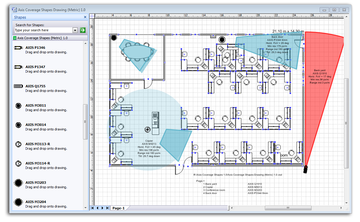
Axis Coverage Shapes for Microsoft Visio helps security system designers decide on the ideal position for each camera by simulating camera coverage based on camera field of view and required resolution.
How it works
Designers can import existing drawings and building layouts or uses the software to draw up the layout of the area they need covered by video surveillance, and then use a simple drag-and-drop function to choose and place cameras directly into the building drawing plans. Realistic, interactive 3D camera models in Autodesk Revit and SketchUp illustrate what the camera set-up will look like in real life, how the cameras integrate with their surroundings, and which area the video surveillance system will cover once installed. Users can choose from a large range of cameras and mounts and place them on any surface in the building plan. Once placed in the design, the software shows the camera's entire field of view as a colored area, with a resolution guide that helps determine the area where the target image solution is met.
To achieve the best coverage with the video surveillance system and optimize the system layout, the software allows designers to try out and compare different camera models, mounting positions and view angles. The software includes controls so users can specify values such as the required focal length, target resolution and mounting height. Users can interactively move the cameras by dragging them to different mounting points and pan or tilt them to determine the camera's field of view for various setups.
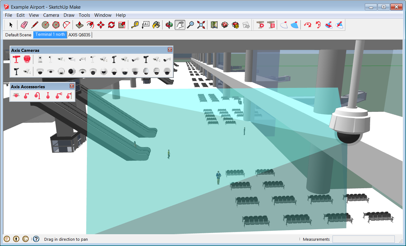
One feature uniquely available for Autodesk Revit and SketchUp is a camera view feature that lets users switch to 3D views as seen from the security camera's point of view, and look through the lens of the camera literally at the click of a button. In SketchUp, this view, the camera can also be rotated or its angle adjusted and the user can see how this changes the field of view from the camera. This allows designers to get a good impression of what the final video surveillance scene will look like at an early stage in the design project, and identify any objects that might obstruct the camera's field of view such as columns or walls.
Once all cameras have been placed in the building design, it is then easy to verify the coverage area for the entire video surveillance solution. These images/scenes can also be used talking to the end user in regards to the systems’ functionality, and help out setting the correct expectations which can then be achieved by the system once installed.
Axis Camera Families for Autodesk Revit offers detailed metadata required for Building Information Modeling (BIM) and allows security system designers to interactively visualize camera coverage.
SketchUp vs Autodesk Revit
SketchUp is a popular and readily accessible 3D CAD software that is particularly easy to use, while Autodesk Revit offers some more advanced and powerful design features that are useful especially in larger design and building projects. To make full use of those, the camera models for Autodesk Revit include detailed metadata required for Building Information Modeling (BIM), a process involving the generation and management of digital representations of physical and functional characteristics of places. They are files which can be exchanged or networked to support decision-making about a place. From inside the CAD drawing, users can access information about each camera such as the model number, focal range, resolution, mounting options and mounting accessories available, as well as power consumption. Once the design is complete, a camera summary lists all cameras used in the design, including any mounting accessories required for the installation.
The advantages
There are a number of benefits in using 3D visualization tools when designing video surveillance systems.
The most obvious benefit is how 3D visualization helps with camera selection and placement. With these tools, system designers have easy access to a complete range of different cameras directly inside the software, including links to relevant technical specifications. By dragging and dropping the cameras in the CAD design and moving them around, they can see what each camera looks like in its environment from a design perspective, and view the camera's coverage for all the different camera types and possible mounting points. This allows them to decide which camera is best suited for the scene that needs to be monitored, and where it should be positioned.
3D visualization tools also help system designers to determine and meet the operational requirements for each video surveillance camera, such as ensuring that the camera has enough resolution, expressed in pixels per foot or per meter to identify a person entering a building through a particular doorway, or to be able to apply intelligent video analytics. With an image resolution guide, the tools provide clear guidance on the image quality that can be expected from each camera in the given setup, and they clearly show the area in the camera's field of view where the required target resolution will be achieved. By exploring using different cameras and mounting options for the video surveillance solution, system designers can make sure that the finished and installed system will not only cover the right areas in or outside the building, but also deliver the required image quality.

With Axis Camera Extension for SketchUp, security system designers can evaluate how cameras fit into the building layout and easily spot if the camera view coverage is obstructed by columns or walls.
Autodesk Revit and SketchUp both include advanced features that let users simulate the movement of the sun throughout the year, and Autodesk Revit can even simulate foliage growth on nearby trees and shrubs. Both are important in understanding the light conditions in which each camera will operate. For example, in winter the sun might be so low that it shines into a camera's lens through a window, or foliage might be so dense in summer that an area in the building becomes very dark or the view from a camera might become obstructed. In both cases, simulating and visualizing the setup will help the system designer decide whether a camera needs to be moved, or a different camera chosen that can cope with difficult light conditions.
Finally, 3D visualization tools are a useful aid for system designers in setting the right expectations with their clients. By demonstrating exactly what the installed system will look like, what it will cover and what camera views to expect, clients will be able to understand the capabilities and limits of the system. The installation and approval process can be streamlined and the list of issues that will need to be fixed before a project can be signed off can be significantly reduced.
Summary
To achieve the best level of security and avoid blind spots that could potentially become a security issue, security systems need to be planned at the same time as other essential services such as electrics and plumbing. With an integrated video surveillance system planning tool, designers can see exactly how the cameras fit into the building layout and can easily detect if views are obstructed by columns or walls, or if the camera installation conflicts with any other building systems such as mechanical, electrical and plumbing installations. This helps to manage customers’ expectations when potential issues can be identified and tackled as early as possible.
With interactive 3D visualization tools like these, architects, engineers and system designers can improve planning and work more efficiently. The result is more effective value engineering, device placement, conflict identification and aesthetic coordination.
- Cover Story
-
 SketchUp Can Help You Win Interior..
 -
 Best Laptops for SketchUp
 -
 How to Resize Textures and Materials..
 -
 Discovering SketchUp 2020
 -
 Line Rendering with SketchUp and VRay
 -
 Pushing The Boundary with architectural
 -
 Trimble Visiting Professionals Program
 -
 Diagonal Tile Planning in SketchUp
 -
 Highlights of some amazing 3D Printed
 -
 Review of a new SketchUp Guide
- Sketchup Resources
-
 SKP for iphone/ipad
 -
 SKP for terrain modeling
 -
 Pool Water In Vray Sketchup
 -
 Rendering Optimization In Vray Sketchup
 -
 Background Modification In sketchup
 -
 Grass Making with sketchup fur plugin
 -
 Landscape designing in Sketchup
 -
 Apply styles with sketchup
 -
 Bedroom Making with sketchup
 -
 Review of Rendering Software
 -
 Enhancing rendering for 3d modeling
 -
 The combination of sketchup
 -
 Exterior Night Scene rendering with vray


