The following is a guide for designing gears in sketchup for 3D printing, CNC milling or similar. For a good introduction in general gear design see here. For an introduction to sketchup see the sketchup related links this page.
A collection of the gears seen in this page can be downloaded from the 3d warehouse.
To begin with, download the involute gear plugin and copy it to your sketchup plugin directory. This plug-in was not produced by me and all credit goes to Cadalog Inc for writing this very useful tool. Then open sketchup and choose ‘Involute Gear’ from the draw menu. From the dialogue box you are presented with three options.
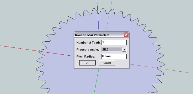
Number of Teeth - The number of teeth on your small gear (pinion gear) relative to your large gear (gear wheel) will determine the gear ratio. If you desire a gear ratio of 2:1 then your gear wheel will have twice as many teeth as your pinion. However, your gear with more teeth would need need to be twice the size in order to have the same sized teeth.
By choosing an even number of teeth you have a range of different exact gear ratios. For example; 12 and 24 (1:2), 12 and 36 (1:3), 12 and 48 (1:4) ect. However, an even number of teeth will result in the same pair of teeth meeting over and over again. By having an odd number of teeth each tooth will meet a different counterpart on every rotation. This helps to distribute lubricant and reduce ware. For example, Wade’s geared extruder has 11 teeth on the pinion and 39 teeth on the gear wheel.
Try and select the highest number of teeth possible while still maintaining a printable resolution. Have no less than 12 teeth and try to avoid a gear ratio any higher than 1:6.
Pressure Angle - The pressure angle effects the geometry of the gear teeth. A low pressure angle (14.5) is normally used with high number of teeth (40+) and will give a greater contact area but lead to increased noise and backlash. Source. I would recomend sticking to a pressure angle of 20. What ever pressure angle you choose, make sure it is constant among all gears used together.
Pitch Radius - This is not the outermost radius of the gear (the root circle). The pitch radius is the distance from the centre of the gear to the ‘pitch point‘, the point of contact between the two gears.
As such, the outermost radius of the gear for a fixed pitch radius will change for different numbers of teeth. However, no matter the number of teeth, the ‘pitch point’ will remain constant for all gears.
The key point here is that if you want two gears to mesh well, then the pitch radius must be increase or decreased by the same ratio as your number of teeth. For example, lets say you have a small gear with 10 teeth and a pitch radius of 10mm. If you wanted a ratio of 1:3 then your large gear would need 30 teeth and pitch ratio of 30mm.
Once you are comfortable with these settings its quite simple to make a range of different gears. When you have finalised your gear design you can export the file as an STL.
Involute Gear - To create an involute gear, use the plugin as described above to first create the gear outline. The gear outline will appear at the point 0,0 so its good idea to mark the centre position before moving it. Add your centre shaft hole and then use the Push/Pull tool (hot key ‘P’) to make the object 3d.
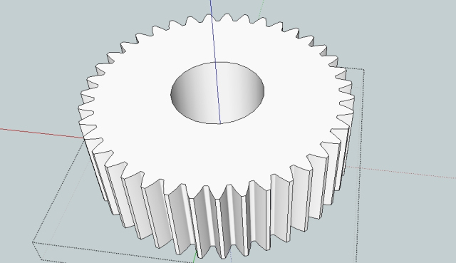
Helical Gear - Make sure the centre of your gear is still positioned at the point 0.0. To create a helical gear simply follow the same process as for the involute gear but with one extra step.
After you have ‘pulled’ your gear surface up to make it 3d, select only the top face of the gear and choose the rotate tool (hot key ‘Q’). With the top face still selected position the protractor over at the centre of the gear and right click. If you have an empty space for a shaft in the centre then just hold down shift while hovering the protractor over a horizontal area to lock it in that orientation. Then its just a matter of choosing your desired angle. For a single helical gear the angle used is normally 6,8,10,12,15,20 degrees. Be aware that a greater angle will result in a greater axial load (see below).
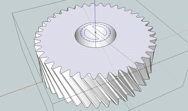
Why would you use a helical gear? They can reduce backlash, ware and noise as opposed to an involute gear. This is due to the gears meshing slowly over their length rather than all at once. However a single helical gear will result in a axial (in the direction of the shaft) load. This can be overcome by using a double helical (herringbone) gear as seen below.
Herringbone Gear (double Helical) - To make a herring bone gear follow the same processes as for the helical gear. Due to elimination of axial loading (see below) higher helical angles can be used. Eg 25,30,35,40 degrees. Select the top face of the helical gear and pull it up so that your gear is now double in height. Then use the rotate tool to rotate it back in the opposite direction as the lower half.
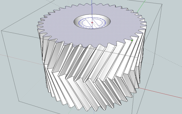
The advantage of the herringbone gear is that all axial forces are cancelled by the opposing helices. This allows for all the advantages of a helix gear with out any of the disadvantages. A herringbone gear will also self centre. Please note that if two herringbone gears are even slightly miss aligned and then fixed in place then they will damage each other. Its best to first fix one gear in place on its shaft while leaving the other free to move parallel to its own shaft. Then turn the fixed gear’s shaft and allow the second gear to ‘self align’ before finally fixing the second gear in place on its shaft.
More information about double helix (herringbone) gears can be found here.
Straight Bevel Gear - To produce a straight bevel make sure you add the shaft hole after making the bevel or else the shaft the wrong shape. Follow the same steps as for the involute gear then select the top face only. Choose the scale tool (hot key ‘S’) and while holding down Ctrl (to scale into the centre) select an outside corner and reduce the top face in size. You will notice that as you do this you change the angle of the gear teeth.
The angle of the gear teeth is important. You can choose any angle so-long as the matching gear has a corresponding angle that together they make up 45 degrees. For example, if the teeth on one gear are at 10 degrees off the vertical then the second gear will need to have teeth that are 35 degrees off their original position.
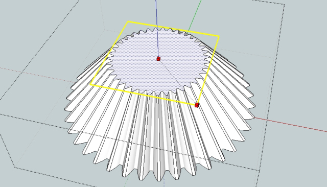
By producing two bevel gears you can transfer mechanical power over 90 degrees. Bevel gears can also be used to change gear ratios. The possible combinations of size and shape are endless so its best just to have a play around in sketchup to get used to it.
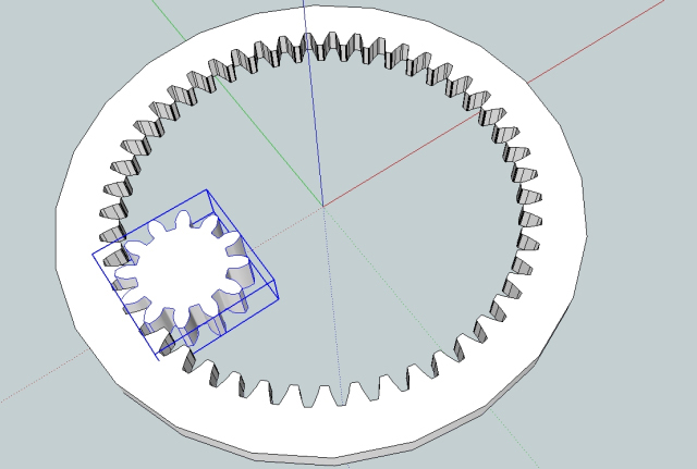
Internal and Planetary (Epicyclic) Gears - The involute gear plugin can also be used for creating internal gears and planetary gears. To create the external gear, first select the circle tool and starting from the origin drag it out to your desired size. This is your external gear. Next, using the involute gear plugin produce a gear with the exact dimensions you desire for the inward facing teeth of your external gear. This will also appear at the origin. Using the pull tool, make the new gear you just created into a 3D object of any height.
The next step is the important one, select the gear ‘group’ (one click on the gear instead of two) and then right click and from the menu choose Intersect -> Intersect with model. There will be a short pause. Once done you can delete the gear group entirely and you will be left with your original circle with the outline of the gear ‘intersected’ into it. From this you can delete the centre face and pull up the outer face to give you your external gear. This can then be populated with other gears to make a planetary gear system or similar.
- Cover Story
-
 SketchUp Can Help You Win Interior..
 -
 Best Laptops for SketchUp
 -
 How to Resize Textures and Materials..
 -
 Discovering SketchUp 2020
 -
 Line Rendering with SketchUp and VRay
 -
 Pushing The Boundary with architectural
 -
 Trimble Visiting Professionals Program
 -
 Diagonal Tile Planning in SketchUp
 -
 Highlights of some amazing 3D Printed
 -
 Review of a new SketchUp Guide
- Sketchup Resources
-
 SKP for iphone/ipad
 -
 SKP for terrain modeling
 -
 Pool Water In Vray Sketchup
 -
 Rendering Optimization In Vray Sketchup
 -
 Background Modification In sketchup
 -
 Grass Making with sketchup fur plugin
 -
 Landscape designing in Sketchup
 -
 Apply styles with sketchup
 -
 Bedroom Making with sketchup
 -
 Review of Rendering Software
 -
 Enhancing rendering for 3d modeling
 -
 The combination of sketchup
 -
 Exterior Night Scene rendering with vray


