Sketchup Resources
- SKP for iphone/ipad
- SKP for terrain modeling
- Pool Water In Vray Sketchup
- Rendering Optimization In Vray Sketchup
- Background Modification In sketchup
- Grass Making with sketchup fur plugin
- Landscape designing in
Sketchup - Apply styles with sketchup
- Bedroom Making with sketchup
- Review of Rendering Software
- Enhancing rendering for 3d modeling
- The combination of sketchup &
BIM - Exterior Night Scene rendering with vray

Author :
Guest Article
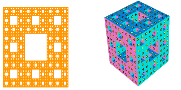
The Sierpinsky Carpet (shown below on the left) is a 2D fractal made from squares repeatedly divided into nine smaller squares. The Menger Sponge (shown below on the right) is the 3D version of this fractal.
For this project, it helps to have some basic knowledge of Google SketchUp (though detailed instructions are provided). In particular, it’s important to know how to zoom, rotate, and pan the view. If you need more information on how to get started, and a description of some basic tools, please read 3DVinci’s Getting Started Guide (PDF).
PC users: go to http://www.3dvinci.net/SketchUp_Intro_PC.pdf.
Mac users: go to http://www.3dvinci.net/SketchUp_Intro_MAC.pdf.
Step 1: Make the Level 1 Cube
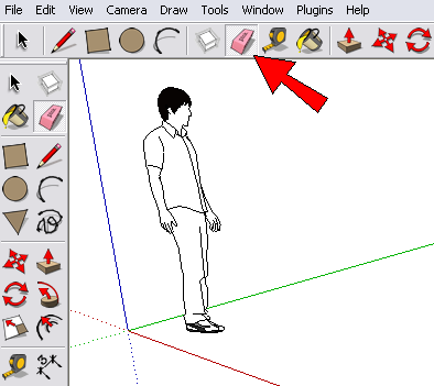
1. Open Google SketchUp. If your file contains a person standing on the ground near the origin, click the Eraser tool and erase him.
2. Switch to Top view (from the main menu, choose Camera / Standard Views / Top). You should see the word “Top” at the top left corner.

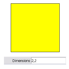
1. We need to start with a cube, and there are many ways to make one in SketchUp. We’ll use the method of setting all edge lengths to an exact dimension. Activate the Rectangle tool and click the first corner of the rectangle. Then move the mouse, and look at the width and height listed in the Dimensions field.
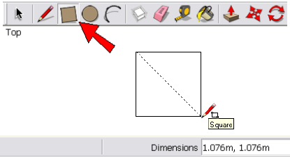
2. Type the dimension you want to use (I’m using 2,2), and the numbers appears in the Dimensions field. Use a number that’s easy to remember. Then press Enter, and the size of the square updates.
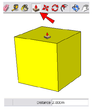
3. Activate Push/Pull, click the square, and pull it up. Type the same dimension you used for the square (2, in my case), and now all edges have the same length.
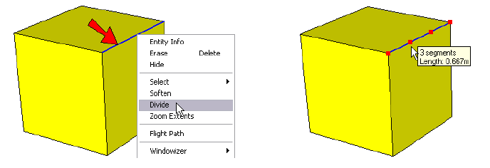
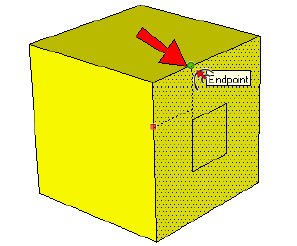
4. The next step is to draw squares on three of the cube faces, which will be used to make a set of cutouts. To define where the first square will be drawn, we first need to divide one edge into three segments. So right-click on the edge shown below on the left, and choose Divide from the popup menu. Move your mouse until you see three segments (as shown below on the right), then click.
5. Activate the Offset tool, and move your mouse to the face below the edge that you divided (don’t click yet). The face should highlight with dots, and the next step is to click along one of the face’s edges. But where you click matters in this case: click anywhere on the left edge (the right edge would also work).
6. Then move your mouse to the endpoint at the one-third point of the divided edge, and click again. You’ve just created a square within a square, whose edges are one-third as long as the edges of the cube face.
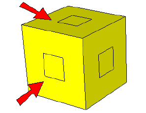
7. With the Offset tool still active, double-click on the other two visible faces of the cube. This creates squares on those face that have the same offset distance.
8. Now use Push/Pull to push each small square through to the opposite side. To make sure the push operation ends at the right place, click any point on the side where you want to stop.
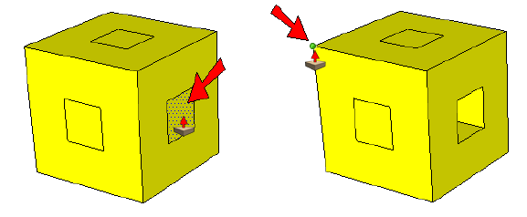
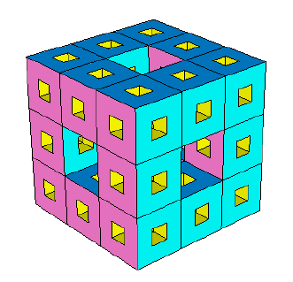
When all three squares have been pushed through, you’ll have a few extra faces in the center of the cube.
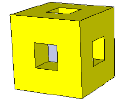
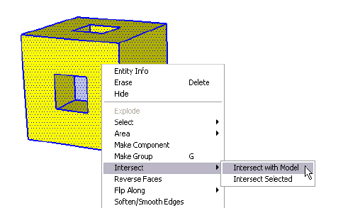
9. Before these faces can be erased, we need to create edges where they meet other faces. So select everything (press Ctrl+A for PC or Cmd+A for Mac), right-click on any selected face, and choose Intersect / Intersect with Model.
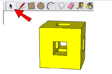
10. You may not be able to tell that any edges were created, but they’re there. Each extra face inside the cube can be erased by first activating the Select tool and clicking on the face, then pressing the Delete key. Look into the cube from the top, bottom, and sides, and make sure all inside faces are erased.
11. Look carefully inside the cube, to see if any faces are missing that shouldn’t be. If you need to replace any faces, just use the Line tool and trace any edge of the missing face.
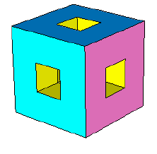
12. To make the final product more interesting, paint the cube. I’m using three colors: one for top and bottom, one for front and back, one for the sides.
Step 2: Level 2, 3, and More
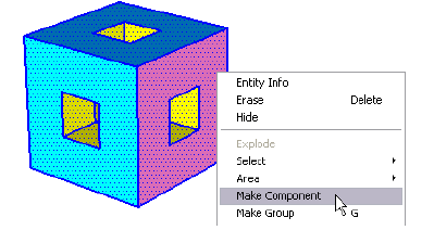
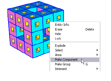
To make the rest of this fractal project much easier, we’ll make this first-level cube into a component. A component is a single object, which will make cubes easier to select, copy, and erase. Components also keep your file size low, since SketchUp will see each new cube as a copy, rather than a whole new set of faces and edges. Once you get to a few fractal levels, the total number of geometric objects will really mushroom, and if you don’t use components, your model may perform slowly.
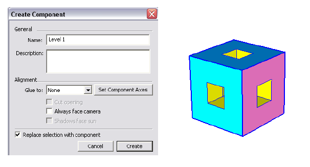
1. Select everything again, right-click on a selected face, and choose Make Compnent.
2. Assign a name (I’m using “Level 1”), and make sure Replace selection with component is checked. Click Create, and the cube is now a single object, outlined in a blue box. This means the cube is selected; leave it selected.
3. We’ll now copy this cube to make a 3 x 3 x cube (27 total cubes). With the cube component selected, activate the Move tool, and to make copies, press the Ctrl key (PC) or Option key (Mac). For the two copy points, click Points 1 and 2 below.
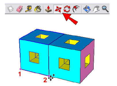
4. Once the first copy is made, type 2x, which appears in the Length field, and press Enter. This makes two copies, or three total cubes.

5. Now select all three cubes and copy them once vertically. Then enter 2x, and you will have nine total cubes.
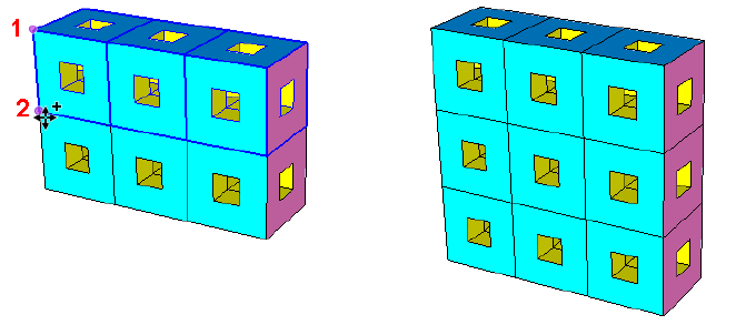
6. Select all nine cubes, and copy them twice to complete the 3 x 3 x 3 cube.
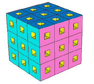
7. The Level 1 cube has cutouts going all the way through from each side, and so must the Level 2 cube. So select and delete seven cubes: one in the center of each of the six cube faces, plus one more at the center of the cube.
8. Now select the entire Level 2 cube and make it a new component.
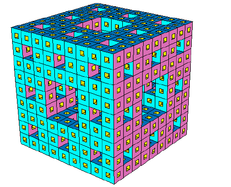
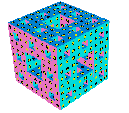
9. Like you did before, make a 3 x 3 x 3 cube, and remove the seven center cubes. Here’s Level 3:
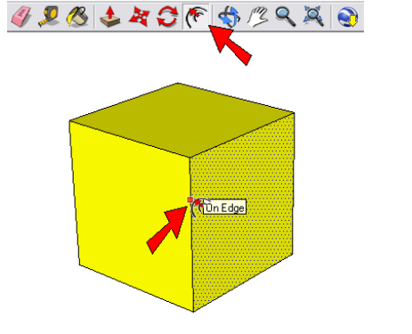
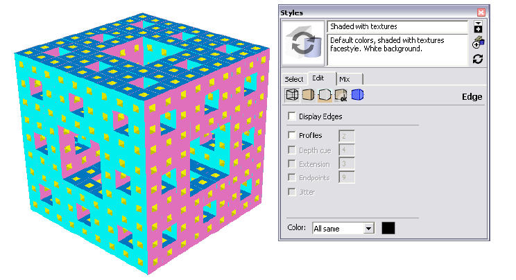
10. If your display seems too cluttered, you can hide the edges. To do this, open the Styles window (main menu: Window / Styles), open the Edit tab, click the Edge icon, and uncheck Display Edges and Profiles.
Another way you can set the display is to hide all edges except the ones around the small cutouts. To do this, you’ll need to edit components progressively downward until you get to the original one. Then use the Eraser tool with the Shift key pressed, and click the 12 outer edges of the cube.
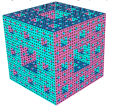
I continued to Level 4, but at this point my model was working very slowly!
Try This
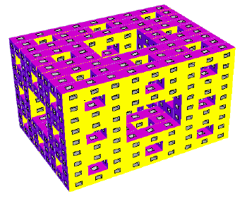
Even though it doesn’t meet the true definition of a Menger Sponge, you can do the same thing with a rectangular prism that has unequal edge lengths:
If you try this project with your children or students, and have an interesting fractal model you’d like to share, please let me know! I
will be happy to blog about it, and possibly mention it in an upcoming newsletter. Contact me at bonnie@3dvinci.net. Thanks!
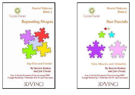
And if you like fractals, you’ll love 3DVinci’s Fractal Patterns books, part of our GeomeTricks series. Check
them out at http://www.3dvinci.net/ccp0-catshow/GM_PDF.html.